(3D-overview)=
# 3D DeepLabCut
In this repo we directly support 2-camera based 3D pose estimation. If you want n camera support, plus nicer optimization methods, please see our new work that was published at [ICRA 2021 on strong baseline 3D models (and a 3D dataset)](https://github.com/African-Robotics-Unit/AcinoSet). In the link you will find how we optimize 6+ camera DLC output data for cheetahs (and see more below).
 ## **ATTENTION: Our code base in this repo assumes you:**
A. You have 2D videos and a DeepLabCut network to analyze them as described in the [main documentation](overview). This can be with multiple separate networks for each camera (less recommended), or one network trained on all views - recommended! (See [Nath*, Mathis* et al., 2019](https://www.biorxiv.org/content/10.1101/476531v1)). We also support multi-animal 3D with this code (please see [Lauer et al. 2022](https://doi.org/10.1038/s41592-022-01443-0)).
B. You are using 2 cameras, in a [stereo configuration](https://github.com/DeepLabCut/DeepLabCut/blob/5ac4c8cb6bcf2314a3abfcf979b8dd170608e094/deeplabcut/pose_estimation_3d/camera_calibration.py#L223), for 3D*.
C. You have calibration images taken (see details below!).
### ***If you need more than 2 camera support:**
Here are other excellent options for you to use that extend DeepLabCut:
## **ATTENTION: Our code base in this repo assumes you:**
A. You have 2D videos and a DeepLabCut network to analyze them as described in the [main documentation](overview). This can be with multiple separate networks for each camera (less recommended), or one network trained on all views - recommended! (See [Nath*, Mathis* et al., 2019](https://www.biorxiv.org/content/10.1101/476531v1)). We also support multi-animal 3D with this code (please see [Lauer et al. 2022](https://doi.org/10.1038/s41592-022-01443-0)).
B. You are using 2 cameras, in a [stereo configuration](https://github.com/DeepLabCut/DeepLabCut/blob/5ac4c8cb6bcf2314a3abfcf979b8dd170608e094/deeplabcut/pose_estimation_3d/camera_calibration.py#L223), for 3D*.
C. You have calibration images taken (see details below!).
### ***If you need more than 2 camera support:**
Here are other excellent options for you to use that extend DeepLabCut:
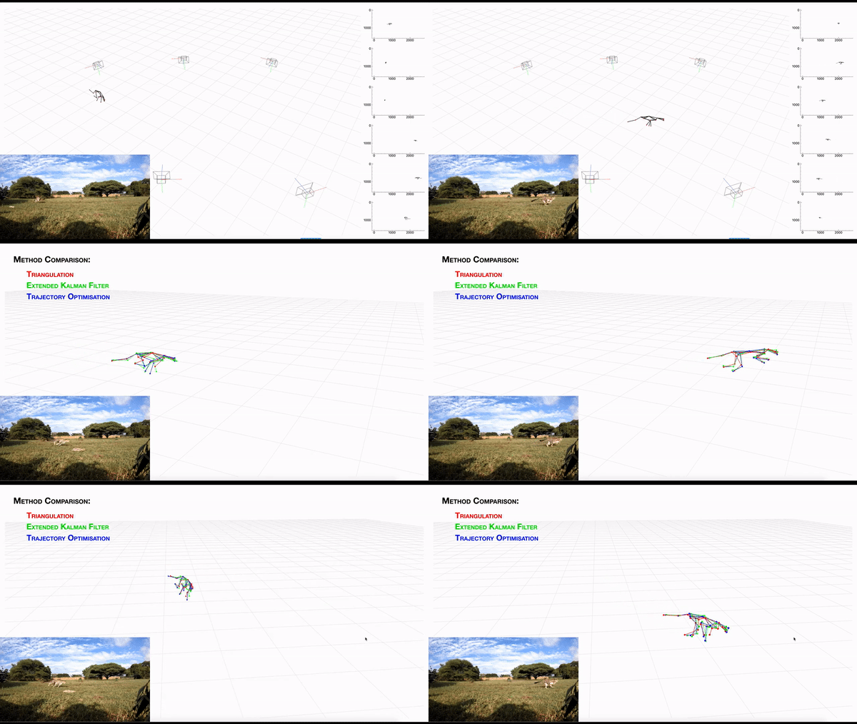 - **[AcinoSet](https://github.com/African-Robotics-Unit/AcinoSet)**; **n**-camera support with triangulation, extended Kalman filtering, and trajectory optimization code (see video to the right for a min demo, courtesy of Prof. Patel), plus a GUI to visualize 3D data. It is built to work directly with DeepLabCut (but currently tailored to cheetah's, thus some coding skills are required at this time).
- **[anipose.org](https://anipose.readthedocs.io/en/latest/)**; a wrapper for 3D deeplabcut that provides >3 camera support and is built to work directly with DeepLabCut. You can `pip install anipose` into your DLC conda environment.
- **Argus, easywand or DLTdv** w/DeepLabCut see https://github.com/haliaetus13/DLCconverterDLT; this can be used with the the highly popular Argus or DLTdv tools for wand calibration.
## Jump in with direct DeepLabCut 2-camera support:
- single animal DeepLabCut and multi-animal DeepLabCut (maDLC) projects are supported:
- **[AcinoSet](https://github.com/African-Robotics-Unit/AcinoSet)**; **n**-camera support with triangulation, extended Kalman filtering, and trajectory optimization code (see video to the right for a min demo, courtesy of Prof. Patel), plus a GUI to visualize 3D data. It is built to work directly with DeepLabCut (but currently tailored to cheetah's, thus some coding skills are required at this time).
- **[anipose.org](https://anipose.readthedocs.io/en/latest/)**; a wrapper for 3D deeplabcut that provides >3 camera support and is built to work directly with DeepLabCut. You can `pip install anipose` into your DLC conda environment.
- **Argus, easywand or DLTdv** w/DeepLabCut see https://github.com/haliaetus13/DLCconverterDLT; this can be used with the the highly popular Argus or DLTdv tools for wand calibration.
## Jump in with direct DeepLabCut 2-camera support:
- single animal DeepLabCut and multi-animal DeepLabCut (maDLC) projects are supported:


### (1) Create a New 3D Project:
Watch a [DEMO VIDEO](https://youtu.be/Eh6oIGE4dwI) on how to use this code, and check out the Notebook [here](https://github.com/DeepLabCut/DeepLabCut/blob/master/examples/JUPYTER/Demo_3D_DeepLabCut.ipynb)!
You will run this function **one** time per project; a project is defined as a given set of cameras and calibration images. You can always analyze new videos within this project.
The function **create\_new\_project\_3d** creates a new project directory specifically for converting the 2D pose to 3D pose, required subdirectories, and a basic 3D project configuration file. Each project is identified by the name of the project (e.g. Task1), name of the experimenter (e.g. YourName), as well as the date at creation.
Thus, this function requires the user to input the enter the name of the project, the name of the experimenter and number of cameras to be used. Currently, DeepLabCut supports triangulation using 2 cameras, but will expand to more than 2 cameras in a future version.
To start a 3D project type the following in ipython:
```python
deeplabcut.create_new_project_3d('ProjectName','NameofLabeler',num_cameras = 2)
```
TIP 1: you can also pass ``working_directory=`Full path of the working directory'`` if you want to place this folder somewhere beside the current directory you are working in. If the optional argument ``working_directory`` is unspecified, the project directory is created in the current working directory.
TIP 2: you can also place ``config_path3d`` in front of ``deeplabcut.create_new_project_3d`` to create a variable that holds the path to the config.yaml file, i.e. ``config_path3d=deeplabcut.create_new_project_3d(...`` Or, set this variable for easy use. Please note that ``config_path3d='Full path of the 3D project configuration file'``.
This function will create a project directory with the name **Name of the project+name of the experimenter+date of creation of the project+3d** in the **Working directory**. The project directory will have subdirectories: **calibration_images**, **camera_matrix**, **corners**, and **undistortion**. All the outputs generated during the course of a project will be stored in one of these subdirectories, thus allowing each project to be curated in separation from other projects.
The purpose of the subdirectories is as follows:
**calibration_images:** This directory will contain a set of calibration images acquired from the two cameras. A calibration image can be acquired using a printed checkerboard and its pair wise images are taken from both the cameras to consider as a set of calibration images. These pair of images are saved as ``.jpg`` with camera names as the prefix. e.g. ``camera-1-01.jpg`` and ``camera-2-01.jpg`` for the first pair of images. While taking the images:
- Keep the orientation of the chessboard same and do not rotate more than 30 degrees. Rotating the chessboard circular will change the origin across the frames and may result in incorrect order of detected corners.
- Cover several distances, and within each distance, cover all parts of the image view (all corners and center).
Use a chessboard as big as possible, ideally a chessboard with of at least 8x6 squares.
- Aim for taking at least 70 pair of images as after corner detection, some of the images might need to be discarded due to either incorrect corner detection or incorrect order of detected corners.
**camera_matrix:** This directory will store the parameter for both the cameras as a pickle file. Specifically, these pickle files contain the intrinsic and extrinsic camera parameters. While the intrinsic parameters represent a transformation from 3-D camera's coordinates into the image coordinates, the extrinsic parameters represent a rigid transformation from world coordinate system to the 3-D camera's coordinate system.
**corners:** As a part of camera calibration, the checkerboard pattern is detected in the calibration images and these patterns will be stored in this directory. Each row of the checkerboard grid is marked with a unique color.
**undistortion:** In order to check for calibration, the calibration images and the corresponding corner points are undistorted. These undistorted images are overlaid with undistorted points and will be stored in this directory.
Here is an overview of the calibration and triangulation workflow that follows:

### (2) Take and Process Camera Calibration Images:
(**CRITICAL!**) You must take images of a checkerboard to calibrate your images. Here are example boards you could print and use (mount it on a flat, hard surface!): https://markhedleyjones.com/projects/calibration-checkerboard-collection.
- You must save the image pairs as .jpg files.
- They should be named with the **camera-#** as the prefix, i.e. **camera-1-01.jpg** and **camera-2-01.jpg** for the first pair of images. Please note, this cannot be changed after the project is created.
**TIP:** If you want to take a short video (vs. snapping pairs of frames) while you move the checkerboard around, you can use this command inside your conda environment (but outside of ipython!) to convert the video to **.jpg** frames (this will take the first 20 frames (set with ``-vframes``) and name them camera-1-001.jpg, etc; edit appropriately):
```python
ffmpeg -i videoname.mp4 -vframes 20 camera-1-%03d.jpg
```
- While taking the images:
- Keep the orientation of the checkerboard the same and do not rotate it more than 30 degrees. Rotating the checkerboard circular will change the origin across the frames and may result in incorrect order of detected corners.
- Cover several distances, and within each distance, cover all parts of the image view (all corners and center).
- Use a checkerboard as big as possible, ideally with at least 8x6 squares.
- Aim for taking at least 30-70 pair of images, as after corner detection, some of the images might need to be discarded due to either incorrect corner detection or incorrect order of detected corners.
- You can take the images as a series of .jpg images, or a video where you post-hoc pair sync'd frames (see tip above).
The camera calibration is an **iterative process**, where the user needs to select a set of calibration images where the grid pattern is correctly detected. The function:``deeplabcut.calibrate_cameras(config_path)``
extracts the grid pattern from the calibration images and store them under the `corners` directory. The grid pattern could be 8x8 or 5x5 etc. We use a pattern of the 8x6 grid to find the internal corners of the checkerboard.
In some cases, it may happen that the corners are not detected correctly or the order of corners detected in the camera-1 image and camera-2 image is incorrect. You need to remove these pair of images from the **calibration_images** folder as they will reduce the calibration accuracy.
To begin, please place your images into the **calibration_images** directory.
(**CRITICAL!**) Edit the **config.yaml** file to set the camera names; note that once this is set, **do not change the names!**
Then, run:
```python
deeplabcut.calibrate_cameras(config_path3d, cbrow=8, cbcol=6, calibrate=False, alpha=0.9)
```
NOTE: you need to specify how many rows (``cbrow``) and columns (``cbcol``) your checkerboard has. Also, first set the variable ``calibrate`` to **False**, so you can remove any faulty images. You need to visually inspect the output to check for the detected corners and select those pair of images where the corners are correctly detected. Please note, If the scaling parameter ``alpha=0``, it returns undistorted image with minimum unwanted pixels. So it may even remove some pixels at image corners. If ``alpha=1``, all pixels are retained with some extra black images.
Here is what they might look like:


Once all the set of images are selected (namely, delete from the folder any bad pairs!) where the corners and their orders are detected correctly, then the two cameras can be calibrated using:
```python
deeplabcut.calibrate_cameras(config_path3d, cbrow=8, cbcol=6, calibrate=True, alpha=0.9)
```
This computes the intrinsic and extrinsic parameters for each camera. A re-projection error is also computed using the intrinsic and extrinsic parameters which provide an estimate of how good the parameters are. The transformation between the two cameras are estimated and the cameras are stereo calibrated. Furthermore, the above function brings both the camera image plane to the same plane by computing the stereo rectification. These parameters are stored as a pickle file named as `stereo_params.pickle` under the directory `camera_matrix`.
Once you have run this for the project, you do not need to do so again (unless you want to re-calibrate your cameras); be advised, if you do re-calibrate, you may want to clearly mark which videos are analyzed with "old" vs. "new" calibration images.
### (3) Check for Undistortion:
In order to check how well the stereo calibration is, it is recommended to undistort the calibration images and the corner points using camera matrices and project these undistorted points on the undistorted images to check if they align correctly. This can be done in deeplabcut as:
```python
deeplabcut.check_undistortion(config_path3d, cbrow=8, cbcol=6)
```
Each calibration image is undistorted and saved under the directory ``undistortion``. A plot with a pair of undistorted camera images with its undistorted corner points overlaid is also stored. Please visually inspect this image. All the undistorted corner points from all the calibration images are triangulated and plotted for the user to visualize for any undistortion related errors. If they are not correct, go check and revise the calibration images (then repeat the calibration and this step)!
### (4) Triangulation --> Take your 2D to 3D!
If there are no errors in the undistortion, then the pose from the 2 cameras can be triangulated to get the 3D DeepLabCut coordinates!
(**CRITICAL!**) Name the video files in such a way that the file name **contains the name of the cameras** as specified in the ``config file``. e.g. if the cameras as named as ``camera-1`` and ``camera-2`` (or ``cam-1``, ``cam-2`` etc.) then the video filename must contain this naming, i.e. this could be named as ``rig-1-mouse-day1-camera-1.avi`` and ``rig-1-mouse-day1-camera-2.avi`` or could be ``rig-1-mouse-day1-camera-1-date.avi`` and ``rig-1-mouse-day1-camera-2-date.avi``.
- **Note** that to correctly pair the videos, the file names otherwise need to be the same!
- If helpful, [here is the software we use to record videos](https://github.com/AdaptiveMotorControlLab/Camera_Control).
- **Note** that the videos do not need to be the same pixel size, but be sure they are similar in size to the calibration images (and they must be the same cameras used for calibration).
(**CRITICAL!**) You must also edit the **3D project config.yaml** file to denote which DeepLabCut projects have the information for the 2D views.
- Of critical importance is that you need to input the **same** body part names as in the config.yaml file of the 2D project.
- You must set the snapshot to use inside the 2D config file (default is -1, namely the last training snapshot of the network).
- You need to set a "scorer 3D" name; this will point to the project file and be set in future 3D output file names.
- You should define a "skeleton" here as well (note, this is not rigid, it just connects the points in the plotting step). Not every point needs to be "skeletonized", i.e. these points can be a subset of the full body parts list. The other points will just be plotted into the 3D space. Here is how the config.yaml looks with some example inputs:

(**CRITICAL!**) This step will also run the equivalent of ``analyze_videos`` (in 2D) for you and then apply a median filter to the 2D data (``filterpredictions=True`` is by default)! If you already ran the 2D analysis and there is a filtered output file, it will take this by default (otherwise it will take your unfiltered 2D analysis files)!
Next, pass the ``config_path3d`` and now the video folder path, which is the path to the **folder** where all the videos from two cameras are stored. The triangulation can be done in deeplabcut by typing:
```python
deeplabcut.triangulate(config_path3d, '/yourcomputer/fullpath/videofolder', filterpredictions=True/False)
```
NOTE: Windows users, you must input paths as: ``r`C:\Users\computername\videofolder' `` or ``C:\\Users\\computername\\videofolder'``.
**TIP:** Here are all the parameters you can pass:
```python
Parameters
----------
config : string
Full path of the config.yaml file as a string.
video_path : string
Full path of the directory where videos are saved.
videotype: string, optional
Checks for the extension of the video in case the input to the video is a directory.
Only videos with this extension are analyzed. The default is ``.avi``
filterpredictions: Bool, optional
Filter the predictions by fitting median (by default) or arima filter. If specified it should be either ``True`` or ``False``.
filtertype: string
Select which filter, 'arima' or 'median' filter.
gputouse: int, optional. Natural number indicating the number of your GPU (see number in nvidia-smi). If you do not have a GPU put None.
See: https://nvidia.custhelp.com/app/answers/detail/a_id/3751/~/useful-nvidia-smi-queries
destfolder: string, optional
Specifies the destination folder for analysis data (default is the path of the video)
save_as_csv: bool, optional
Saves the predictions in a .csv file. The default is ``False``; if provided it must be either ``True`` or ``False``
```
The **triangulated file** is now saved under the same directory where the video files reside (or the destination folder you set)! This can be used for future analysis. This step can be run at anytime as you collect new videos, and easily added to your automated analysis pipeline, i.e. such as **replacing** ``deeplabcut.triangulate(config_path3d, video_path)`` with ``deeplabcut.analyze_videos`` (as if it's not analyzed in 2D already, this function will take care of it ;):

### (5) Visualize your 3D DeepLabCut Videos:
In order to visualize both the 2D videos with tracked points plut the pose in 3D, the user can create a 3D video for certain frames (these are large files, so we advise just looking at a subset of frames). The user can specify the config file, the **path of the triangulated file folder**, and specify the start and end frame indices to create a 3D labeled video. Note that the ``triangulated_file_folder`` is where the newly created file that ends with ``yourDLC_3D_scorername.h5`` is located. This can be done using:
```python
deeplabcut.create_labeled_video_3d(config_path, ['triangulated_file_folder'], start=50, end=250)
```
**TIP:** (see more parameters below) You can set how the axis of the 3D plot on the far right looks by changing the variables ``xlim``, ``ylim``, ``zlim`` and ``view``. Your checkerboard_3d.png image which was created above will show you the axis ranges. Here is an example:

``View`` is used to set the elevation and azimuth of the axes (defaults are [113, 270], and you should play around to find the view-point you like!). Also note that the video is created from a set of .png files in a "temp" directory, so as soon as you run this command you can open the first image, and if you don't like the view, hit ``CNTRL+C`` to stop, edit the values, and start again!
**Other optional parameters include:**
```python
videofolder: string
Full path of the folder where the videos are stored. Use this if the vidoes are stored in a different location other than where the triangulation files are stored. By default is ``None`` and therefore looks for video files in the directory where the triangulation file is stored.
trailpoints: int
Number of previous frames whose body parts are plotted in a frame (for displaying history). Default is set to 0.
videotype: string
Checks for the extension of the video in case the input is a directory.
Only videos with this extension are analyzed. The default is ``.avi``
view: list
A list that sets the elevation angle in z plane and azimuthal angle in x,y plane of 3d view. Useful for rotating the axis for 3d view
xlim: list
A list of integers specifying the limits for xaxis of 3d view. By default it is set to [None,None], where the x limit is set by taking the minimum and maximum value of the x coordinates for all the bodyparts.
ylim: list
A list of integers specifying the limits for yaxis of 3d view. By default it is set to [None,None], where the y limit is set by taking the minimum and maximum value of the y coordinates for all the bodyparts.
zlim: list
A list of integers specifying the limits for zaxis of 3d view. By default it is set to [None,None], where the z limit is set by taking the minimum and maximum value of the z coordinates for all the bodyparts.
```
### If you use this code:
We kindly ask that you cite [Mathis et al, 2018](https://www.nature.com/articles/s41593-018-0209-y) **&** [Nath*, Mathis*, et al., 2019](https://doi.org/10.1038/s41596-019-0176-0). If you use 3D multi-animal: [Lauer et al. 2022](https://doi.org/10.1038/s41592-022-01443-0).